Detect
The published sketch reads one digital flame-sensor input on D5. Two sensor modules are shown in the project materials.
Automatic fire detector
A BAI hardware build that reads a flame sensor, then drives a pump, warning light, and recorded voice alert through an ESP8266 controller.
01 / PROJECT OVERVIEW
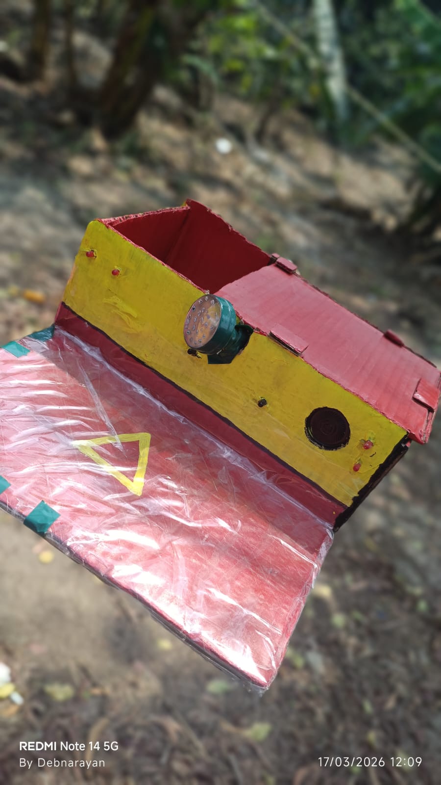
This prototype connects flame sensing to a physical response: an ESP8266 switches the pump relay, plays a recorded warning, flashes an LED, and can log a Blynk event.
The published sketch reads one digital flame-sensor input on D5. Two sensor modules are shown in the project materials.
The ESP8266 sketch maps D1 to the relay, D2 to the voice module, and D6 to the LED indicator.
On a LOW flame reading, the sketch activates the relay and voice output, blinks the LED, and logs a Blynk event.
02 / SIGNAL FLOW
The drawing below follows the pin assignments in the published sketch. It describes the signal path; use the supplied circuit diagram and module datasheets to confirm physical wiring.
Read the firmware pin map03 / PARTS DOCUMENTED IN THIS PROJECT
Quantities and details below come from the project page, wiring diagram, firmware sketch, and prototype photos. Where those sources are incomplete or disagree, the row says so.
Required build parts
Runs the published fire-detection, relay, voice-alert, LED, and Blynk sketch.
Switches the water-pump motor from the controller output.
The project page and diagram show a pair of modules for flame detection.
Provides the recorded voice warning triggered by the project sketch.
The project page describes a mini pump; the diagram labels a 12V DC motor.
Visual warning indicator listed in the project and shown in the wiring diagram.
Series resistor labelled beside the LED in the wiring diagram.
Audio output transducer connected to the ISD1820 module in the diagram.
Separate source labelled for the voice module in the wiring diagram.
Supplies the 12V motor/pump path shown in the project diagram.
Build accessories
Wiring accessories are listed in the project and visible in the prototype photos.
Tubing is described as part of the prototype and visible in its photos.
No optional electronic parts or enclosure cut list are documented. The handmade enclosure visible in the photos is not itemized because its material and dimensions are unknown. The BOM is a guide to the recorded prototype; confirm the actual parts and datasheets before ordering or powering the circuit.
04 / PROTOTYPE & WIRING
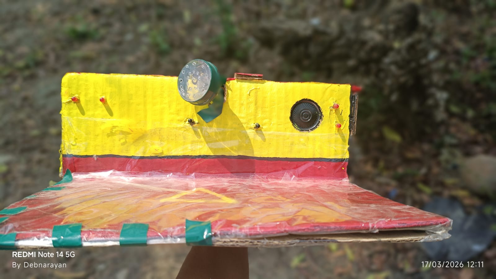
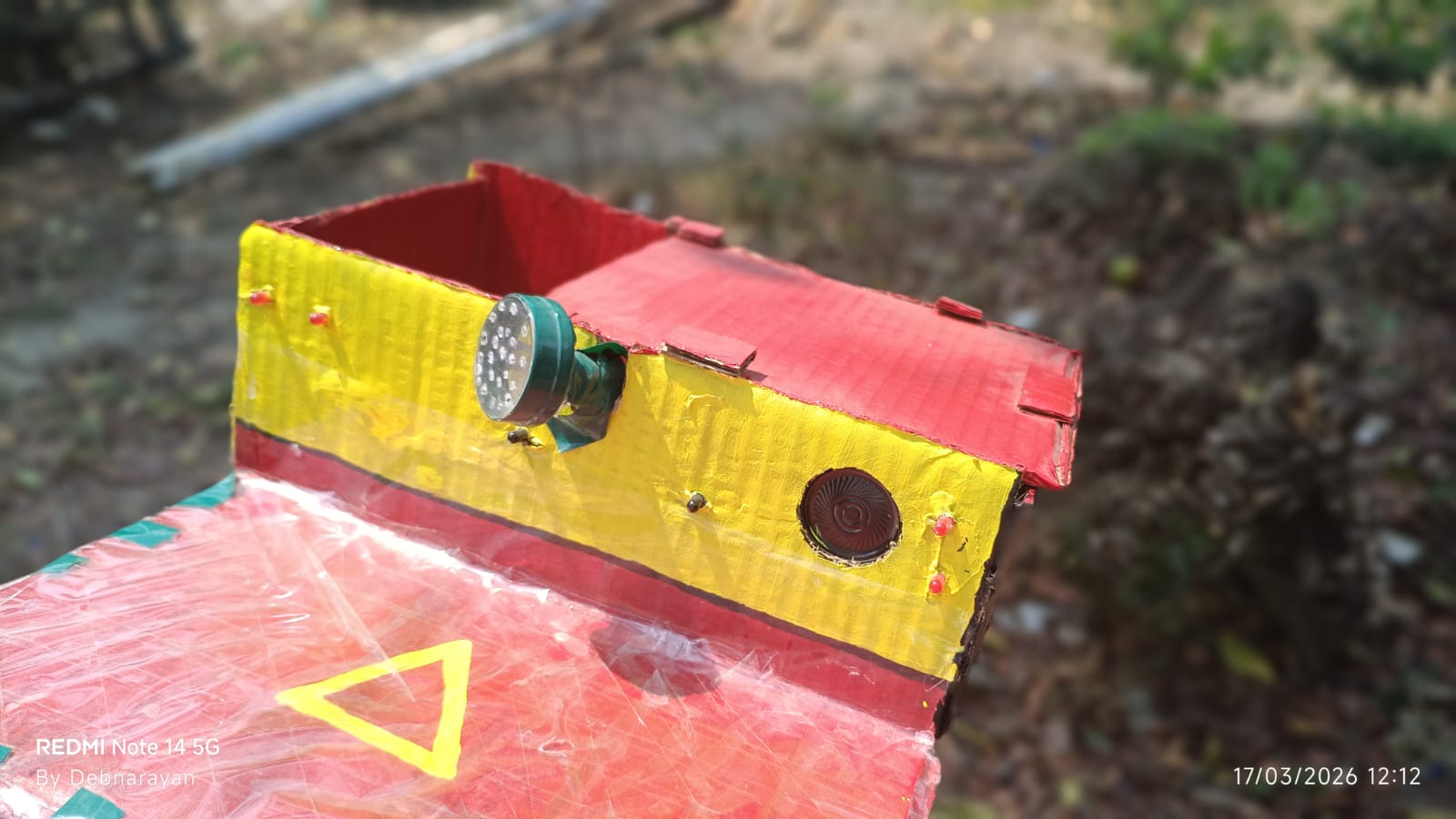
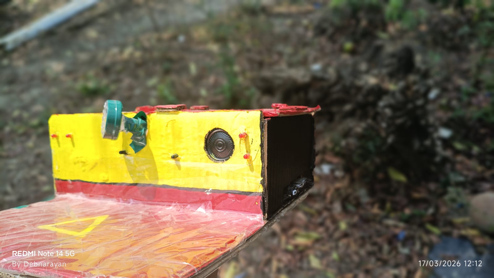
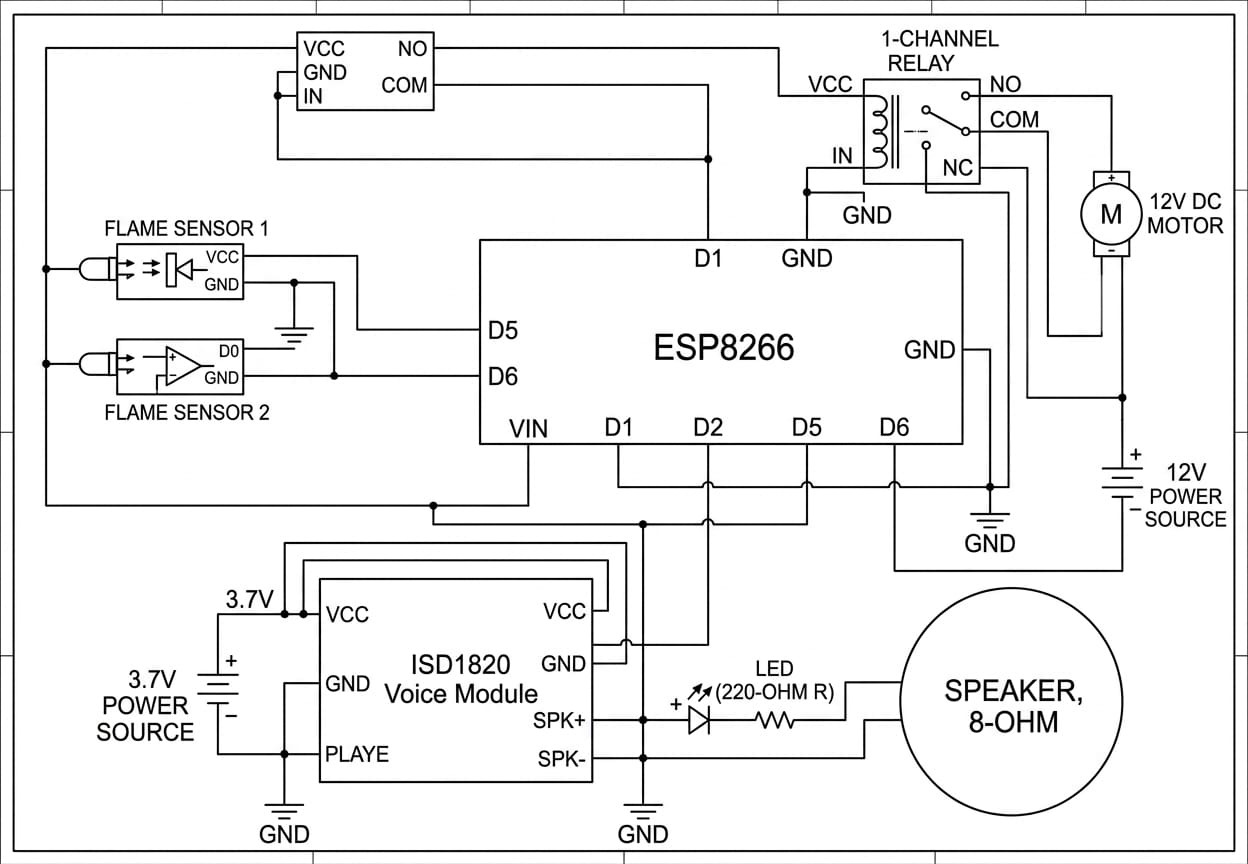
Browse the physical model and original circuit drawing. The connection notes below follow the published code and flag the pin conflict that still needs review.
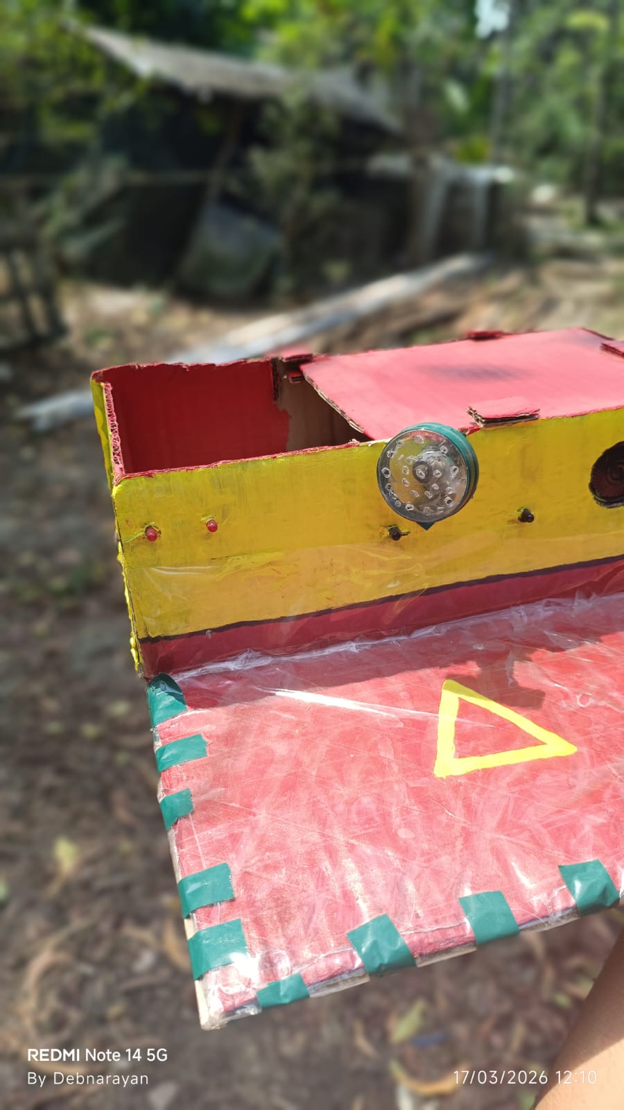
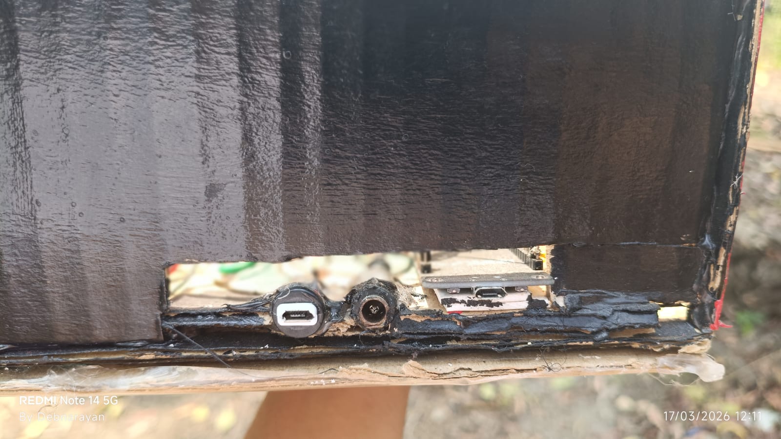
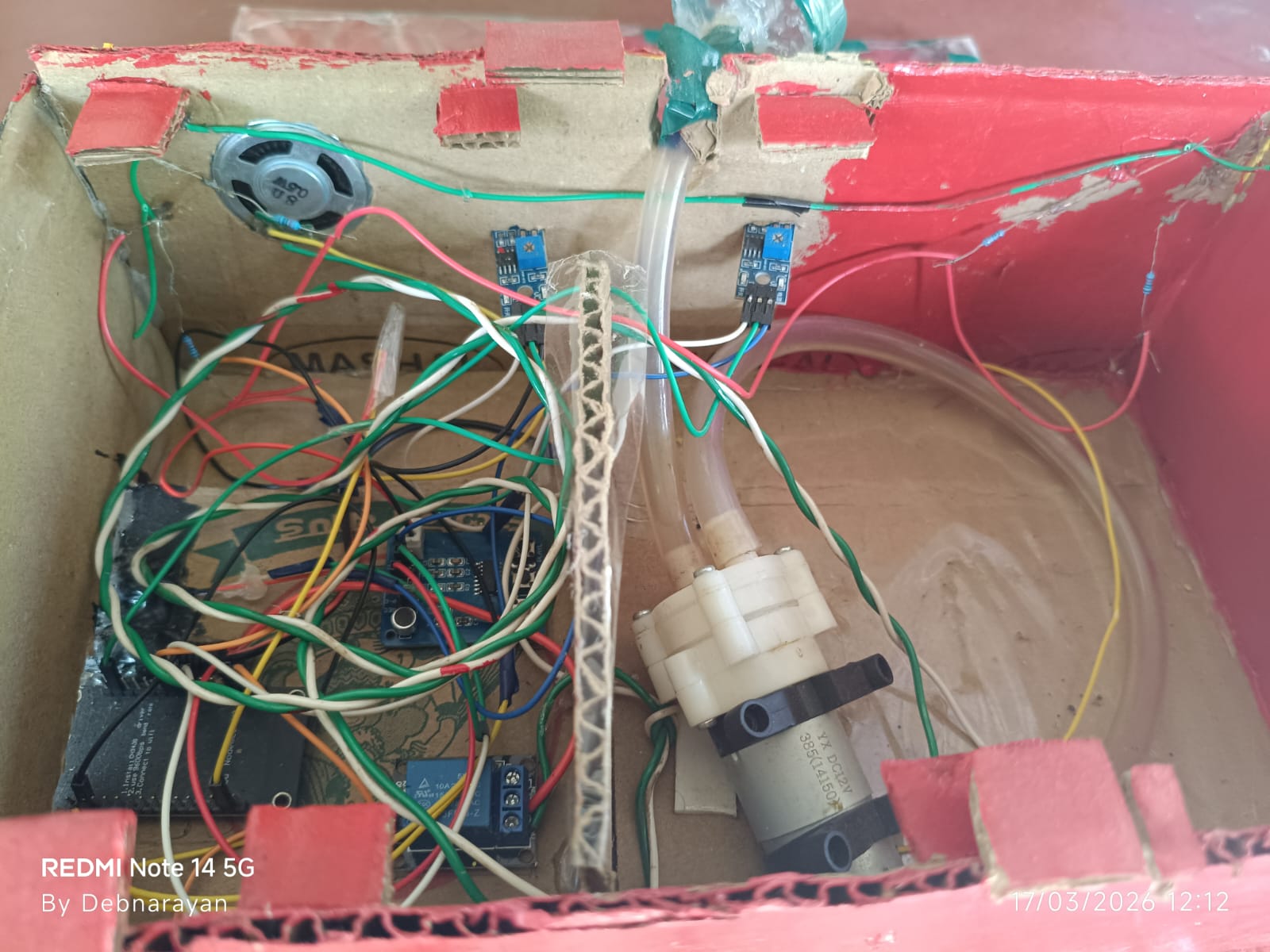
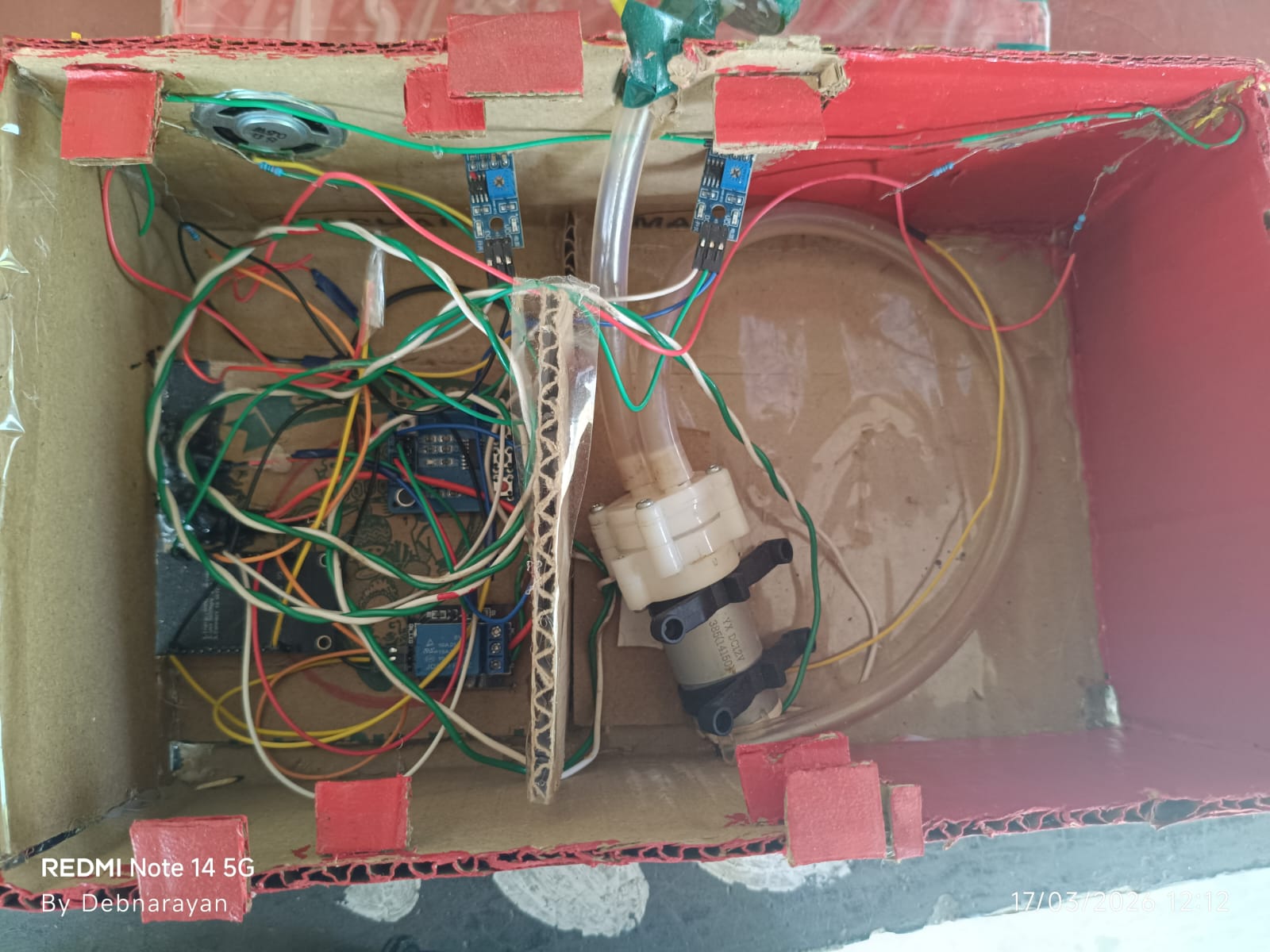
 Download Diagram
FIRMWARE REFERENCE
digitalRead.The wiring diagram shows a second flame sensor at D6. That does not match the published sketch; verify the intended wiring and firmware before use.
05 / CONTROLLER SKETCH
Use the template as a project reference. Add your own Blynk and Wi-Fi values before uploading.
Replace the template values with your Blynk credentials, then connect your Wi-Fi details before uploading the code.
#define BLYNK_TEMPLATE_ID "Enter Your Template ID"
#define BLYNK_TEMPLATE_NAME "Enter Your Template Name"
#define BLYNK_AUTH_TOKEN "Enter Your Blynk Auth Token"
#define BLYNK_PRINT Serial

#include <ESP8266WiFi.h>
#include <BlynkSimpleEsp8266.h>

char ssid[] = "Your WiFi Name";
char pass[] = "Your WiFi Password";

#define FLAME_PIN D5
#define RELAY_PIN D1
#define ISD_PLAY  D2
#define LIGHT_PIN D6

bool fireNotified = false;
unsigned long lastBlinkTime = 0;
bool lightState = false;

void setup() {
  Serial.begin(9600);
  Blynk.begin(BLYNK_AUTH_TOKEN, ssid, pass);

  pinMode(FLAME_PIN, INPUT);
  pinMode(RELAY_PIN, OUTPUT);
  pinMode(ISD_PLAY, OUTPUT);
  pinMode(LIGHT_PIN, OUTPUT);

  digitalWrite(RELAY_PIN, LOW);
  digitalWrite(ISD_PLAY, LOW);
  digitalWrite(LIGHT_PIN, LOW);
}

void loop() {
  Blynk.run();

  int flameState = digitalRead(FLAME_PIN);
  unsigned long currentTime = millis();

  if (flameState == LOW) {
    digitalWrite(RELAY_PIN, HIGH);
    digitalWrite(ISD_PLAY, HIGH);

    if (currentTime - lastBlinkTime >= 250) {
      lastBlinkTime = currentTime;
      lightState = !lightState;
      digitalWrite(LIGHT_PIN, lightState);
    }

    if (!fireNotified) {
      Blynk.logEvent("fire_alert", "Fire Alert! Fire Detected!");
      fireNotified = true;
    }
  } else {
    digitalWrite(RELAY_PIN, LOW);
    digitalWrite(ISD_PLAY, LOW);
    digitalWrite(LIGHT_PIN, LOW);
    fireNotified = false;
  }
}The internal setup includes the controller board, relay, speaker, flame sensor modules, pump, and tubing arranged inside a hand-built enclosure. This makes the project both presentable and functional.
Debnarayan Dhara
Vaskar Das